I have a decent (but aging) surround receiver connected to my HTPC - a Pioneer VSX-2016av. Because of it's age it really doesn't have any good ways to control it from a PC (USB or even serial).
As part of my home automation setup it would be great to be able to control some of the features on the receiver. Volume up, volume down, power off, power on, etc.. Most of the time I use a wireless keyboard as an interface to my HTPC (running XBMC) - and the remote control for the receiver is only really used for volume control. Would love to be able to control these directly from the keyboard.
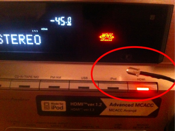
I've tried to control this receiver via IR, and actually set up a microcontroller to record the IR signal from the remote today. After decoding the modulated (38 khz) pulses I was able to play back the same signal and do stuff on the receiver from a microcontroller via IR. This could work.. but you actually have to point the IR diode more or less directly at the front of the receiver - reflections doesn't work (maybe I could try a more powerful LED?). Was thinking about mounting the LED directly on the receiver, but it looks ugly :(
Then I noticed the SR-link (in and out) ports on the back of the receiver. It's a system Pioneer (and some other companies?) use for linking hifi/video equipment. You can use it to relay IR control and even transfer configuration options (in SR+). So I hooked up a microcontroller to the SR input port - you can use a mono 3.5" jack - signal is on the middle pin. Ground can be taken directly from the chassis (shield on RCA-port for example).
Spent a while experimenting with this, by listening to the SR-output port while using the remote control. The signal is high (5v) as default, and pulled low on every IR pulse. Tried to replicate this using a microcontroller connected to SR Input on the receiver - wasted a lot of time beliving the signal should be 38 khz modulated - just like IR - but alas - no need for modulation - it won't actually work if you modulate. Finally got it working - awesome! Now I can control my receiver from a microcontroller.
My goal is to get this directly connected to a Raspberry PI (which is going to be the HUB of my home automation system). If I can I really want to skip the microcontroller - and do it directly from the rasp-pi. I ported my microcontroller code to the PI, but it seems that I can't get the timing accurate enough (running in userland).
Microsecond timing accuracy is a bitch in linux, I guess I could do this in kernel space - but that's a lot of effort. Guessing I'll probably have to go the microcontroller route. Also wish I had a decent scope, so that I could see how much jitter I'm dealing with here.
#include <stdio.h>
#include <stdlib.h>
#include <errno.h>
#include <fcntl.h>
#include <sys/mman.h>
#include <errno.h>
#include <stdint.h>

// SR Control pulses (IR pulses without modulation)
#define HDR_MARK    9000
#define HDR_PAUSE   4500
#define BIT_MARK    560
#define ONE_PAUSE   1600
#define ZERO_PAUSE  560

// SR Control codes:
#define SR_VOLUME_UP    0xA55A50AF
#define SR_VOLUME_DOWN  0xA55AD02F
#define SR_TOGGLE_PWR   0xA55A38C7
#define SR_INPUT_HDMI   0xA55A7A85

static volatile uint32_t *gpio;

void sendCode(unsigned long data, int nbits);
void sendPulse(long microsecs);

int main(int argc, char **argv)
{
	int fd, i;

	// Open memory handle
	if ((fd = open ("/dev/mem", O_RDWR | O_SYNC) ) < 0) {
		printf("Unable to open /dev/mem: %s\n", strerror(errno));
		return -1;
	}

	// map memory to gpio at offset 0x20200000 (gpio start..)
	gpio = (uint32_t *)mmap(0, getpagesize(), PROT_READ|PROT_WRITE, MAP_SHARED, fd, 0x20200000);

	if ((int32_t)gpio < 0){
		printf("Mmap failed: %s\n", strerror(errno));
		return -1;
	}

	//set gpio17 as an output
	*(gpio + 1) = (*(gpio + 1) & ~(7 << 21)) | (1 << 21);

	//set gpio17 high:
	*(gpio + 7) = 1 << 17;
	sleep(1);

	for (i = 0; i < 5; i++) {
		sendCode(SR_VOLUME_UP, 32);
		sleep(1);
		sendCode(SR_VOLUME_DOWN, 32);
		sleep(1);
	}
}

void sendPulse(long microsecs)
{
	// Take GPIO 17 low, wait, then high. (one pulse..)
	*(gpio + 10) = 1 << 17;
	usleep(microsecs);
	*(gpio + 7) = 1 << 17;
}

void sendCode(unsigned long data, int nbits)
{
	int i;

	sendPulse(HDR_MARK);
	usleep(HDR_PAUSE);

	for (i = 0; i < nbits; i++)
	{
		sendPulse(BIT_MARK);

		if (data & 0x80000000)
			usleep(ONE_PAUSE);
		else
			usleep(ZERO_PAUSE);

		data <<= 1;
	}
}
11 comments
This doesn't help your "not writing kernel drivers" part but it may be possible to get a bit more hardware support for this from the RPi if you are willing to sacrifice your analogue audio output. Each of the two PWM peripherals that normally drive the audio also have a "serialise" mode that will clock out data from a FIFO at the rate of the clock supplied to it (page 140 or so in the datasheet).
So to get your 1usec pulses you'd also want a 1MHz clock to the PWM rather then the 100MHz (?) used by the audio driver.
Then you can presumably write 32 bits at once to that register / FIFO (DAT1, DAT2 or FIF1).
(Chip) Pin 18 in the RPi's GPIO block can be configured to be PWM0 output so it ought to be possible to get at this signal without any soldering either.
Probably.
This might be a good start: https://github.com/richardg...
Thanks Ross, that would be a pretty cool hack - i didn't know they did audio that way on the PI, great tip!
(..also the panalyzer project from the same guy as the servoblaster was pretty cool)
You could also try this approach:
https://projects.drogon.net...
He says it can generate delays on the order of microseconds, which should be good enough if I understand the protocol correctly. Please post a followup if you try it. I probably won't be able to try it myself for a few months.
Oh! That's pretty cool as well, I will try that if I find the time.
I got back to this a little sooner than expected and also came across a gpio-based lirc kernel module for the pi (lirc_rpi). It is now included in the official linux sources. Unfortunately the sr protocol is inverted compared to an ir diode. The receiver works out of the box but you need a patch for the transmitter, which is included in my fork:
https://github.com/pjenning...
That is awesome!
It works with any of the gpio pins I assume?
Do you plan to create a pull request for the invert patch, to get it into the mainstream rpi kernel?
I only tested it on one pin, but it was not the default pin so I assume it would work on any of them. I just submitted a pull request.
Hi guys,
This is really huge. I was exactly going to do the same with an IR Led Transmitter when I saw the IR IN/OUT at the back of my home surround receiver.
I’ve checked on the Pi Kernel and it seems that’s Paul’s pull request has been accepted : https://github.com/raspberr...
Now, I do have some questions which might look for you as newbie question but :
* How do I set to the lirc_rpi module to go in the inverted mode in ordrer do work ? Do we have to do “modprobe lirc_rpi invert=1″ ?
* Regarding the hardware do you just have to put a jack connector between GPIO17 and the ground ? Or do we have to deal with this kind of hardware (http://1.bp.blogspot.com/-D... after replacing the LED by the jack
Thanks for your help !
Arnaud
Hi, is there any Chance to get a step-by-step Manual for Linux-noobs? I am using a RPi with FHEM as my smart home Gateway and would love to get around glueing a IR LED on the Receiver...
I could also use an Arduino or something similar, but I´d Need a bit more info on what to do with the code you supplied above.
It is possible to public the microcontroller code? As you mentioned:Finally got it working - awesome! Now I can control my receiver from a microcontroller.
Hi, thanks for the tutorial and the code.
I am trying to replicate this, but when I plug 3.5mm jack to "control in", I can't use the remote and my SR codes don't work. I think I am wiring something wrong. Can you post a simple schematic what is connected to what? How you connect jack and ground from RCA connector with the microcontroller?